
We go on deeper in the jungle. In this post I will show you that a motor’s datasheet is not always meant to help you starting a fire in your fireplace or to be thrown at a random colleague through the open-space. I explain here how to actually read and understand a motor’s datasheet.
Anyone who knows the basics of DC motors can read this. If you feel that you miss some knowledge, go have a look to the previous posts in this serie (guide to motors in robotics, and controlling a DC motor’s direction and speed).
While working with DC motors, you’ll be more than likely to deal with datasheets / specifications files. Many retailers provide them to define the specifications of their motors, in order to properly use them. This is how it may look:
Here I want to divide this datasheet in 3 sections.
Section 1: General dimensions of motor. This part is very useful for motor integration in the robot environment. You can see where to put screws, what length and diameter is the shaft, etc. Weight is also a good thing to know, and often a critical issue in robotics. I won’t talk more about this section here, because, well, dimensions are dimensions and that’s it.
Section 2: Here are the specifications of the motors, sometimes presented as a table. Again according to which retailer provides the information, you can find either many things (not always useful though) or either almost nothing. But some of these specs are necessary for the good understanding of the motor. We will see in a short while which specs are the most important.
Section 3: Characteristic curves. Sometimes you find them, sometimes not. They are useful to have a global view of your motor’s performances. I will explain them later in this post as well.
First, the basics
Some useful facts, always good to keep in mind:
- A motor absorbs energy in the form of current and voltage, so a motor’s datasheet will provide various electronic specifications.
- It delivers energy in the form of rotational movements (and a bit of heat). The movements imply speed and torque.
Note: A torque is a rotational force. It means a force applied at a distance from a pivot. Its expression is a force multiplied by a distance.
A simple way to put it is the force you apply to a screwdriver while screwing a screw.
- A DC motor has two main ranges of use: continuous use and intermittent (or short-term) use (a third one is a no-go zone). The first one allows you to make it rotate during long periods of time, while the second one only allows short periods of time rotating, until it heats too much.
Now, the minimum spec list
There are a minimum of three critical specs in the section 2 you will need if you want to know well your motor and properly use it:
- Nominal voltage (Unom)
- No-load speed (S0)
- Stall torque (Tstall)
Why only these three are the most important, while a bunch of other strange words and values are orbiting around them?
Because every result you want to produce with a motor is dependent to speed or torque — or ultimately to both of them. And at a given voltage, speed and torque are tightly linked together. We will come back to that in a minute.
- Nominal voltage: This is at the same time the voltage at which the other specs were measured, and the suggested voltage at which the performances are the best, most of the time. You can consider using the motor with the nominal voltage without any problem, or a at value above it. Be advised that a too high voltage will result in damaging the coils.
Also, the voltage is directly proportional to the speed of the motor (as you read in previous posts).
- No-load speed: Exactly as it is named, this is the rotational speed of the motor’s output when no load is applied to it, i.e. when nothing is linked to the output. This is the maximal speed the motor can reach at a given voltage.
- Stall torque: It is the maximal torque that can be applied to the rotor until it stops spinning.
The faster a motor rotates, the lesser torque it provides — and vice versa.
There is a simple experiment to check that deep truth at home: take a small DC motor and apply a low voltage to its terminals. Now grab the shaft and try to stop it spinning: the more “force” (actually torque) you apply to the output, the slower the rotor turns; and finally it stops, until you release that poor fellow.
Note: Don’t try this a too long time — i.e. no more than a second, or two. A powered motor that is not rotating is like a power supply connected to a coil: the wires will quickly heat, its insulating sleeve will melt, the whole thing will expand a bit and might burn a lot.

What do these three specs tell you? They give you the theoretical range of use of your motor. You know that for optimal performance, the motor must be supplied by the given nominal voltage. Also, you know what are its maximal speed and the maximal load it can bear (1). Of course no-load speed and stall torque are extreme values (theoretically impossible to reach), and it’s better not to push the motor close to these limits if you want to ensure a good dynamic. A motor never works well at its extreme values.
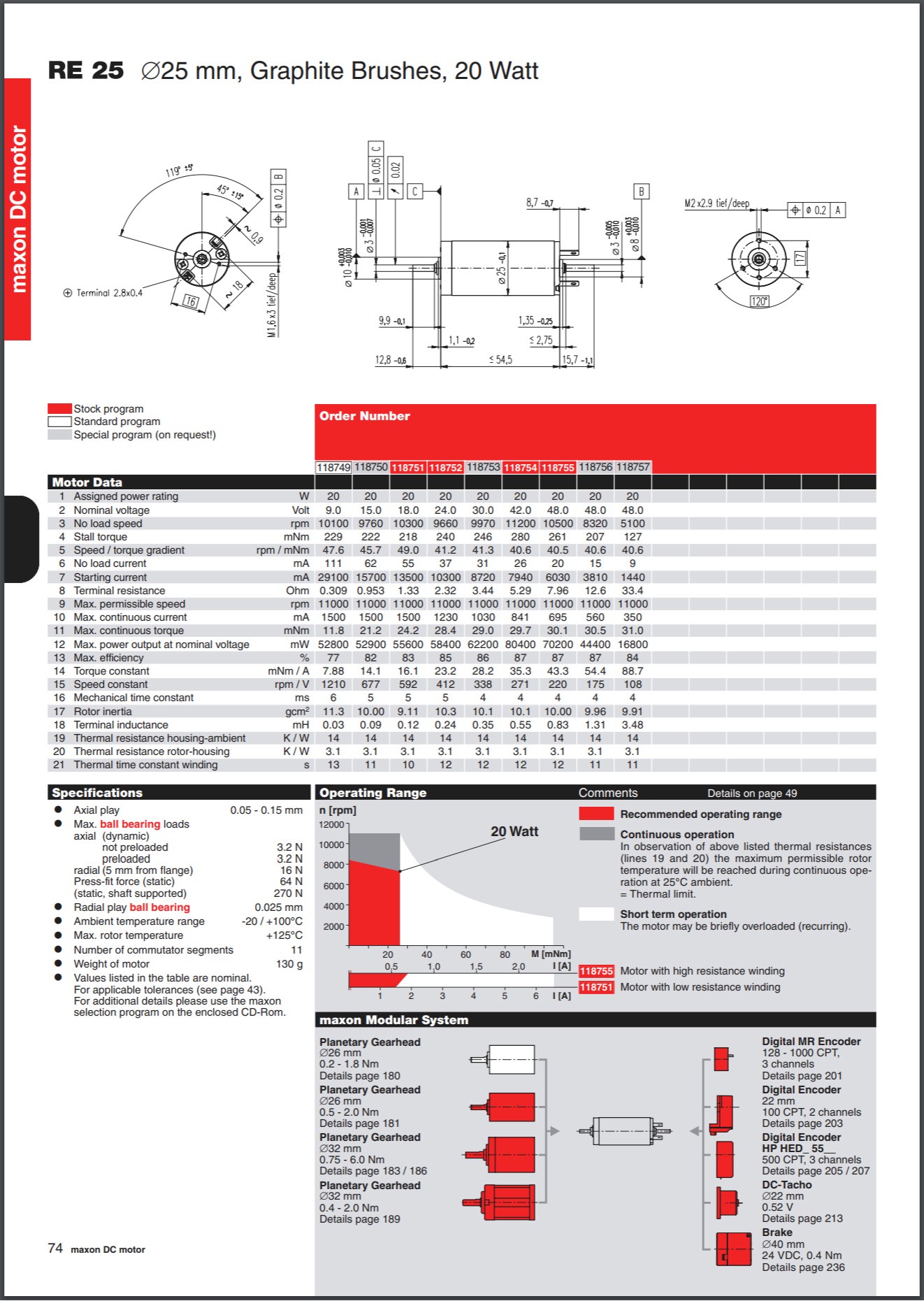
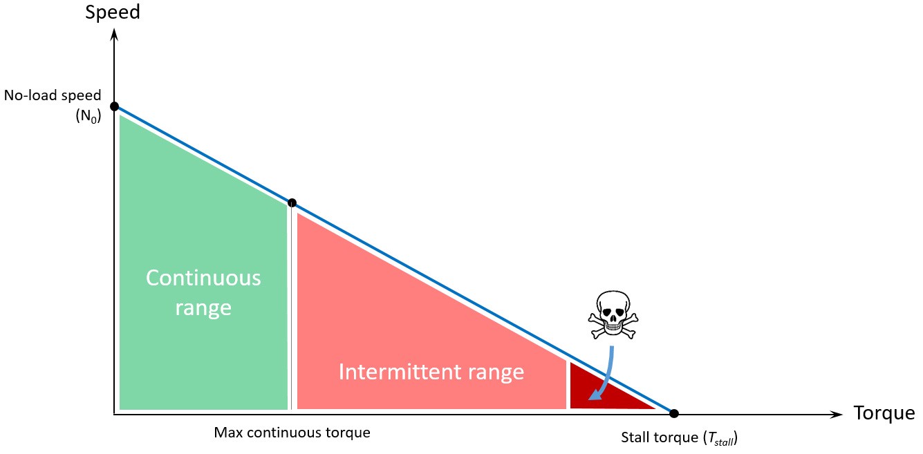
The basic curve and the ranges of use
According to what we just learnt, this is how it looks like on a simpler characteristic curve:
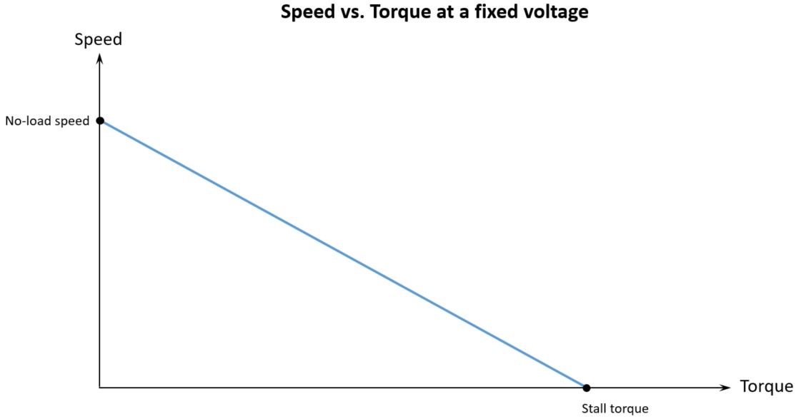
Note: This curve is shown for a given fixed voltage. If you change the voltage, it will appear parallel to the original, but above it for higher voltage or under it for lower voltage:
If there is what I called earlier a section 3 on your datasheet, then it must provide this particular curve (or part of it at least). Some other curves can appear as well, we will see that later on this post.
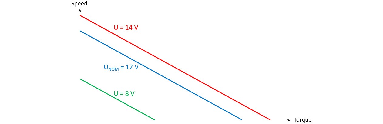
As you can see, the rotating speed is at its maximum when there is no load on the shaft, this is the no-load condition. Then it decreases while the load increases. At the right of the curve, a maximum load implies no speed at all. This is the stall condition.
The curve represents actually a lot of functioning points associated to the motor. For example, a motor at 12 V with a given load of 5 mN.m will have a given speed of 400 rpm (2):
Note: Keep in mind that this is a theoretical behavior; it means that there always will be some small divergence if you try this with an actual motor, due to external conditions, building quality, ranges of precision.
Finally, a motor can’t virtually be used on its whole speed-torque curve. There is a virtual limit separating the continuous to the intermittent ranges. While you can use your motor as much as you want on the first range, the second one is likely to make your motor heat and to damage it if you keep too long into this range. This limit, called maximum continuous torque, can be observed most of the time around the value of Stall torque / 3, but this isn’t a golden rule.
The other specs
Let’s go back to section 2, the specs. There are some other important specs that come just after the three ones we talked about earlier. Here is a list of the ones that come just after:
- No-load current: Current consumed by the motor while continuously rotating at no-load speed.
- Starting (or stall) current: Current consumed by the motor at stall torque condition. This current is observed as a peak when a rotor stars rotating.
- Rated (or continuous) speed, torque and current: These three values are linked together and define a functioning point of your speed-torque curve. This is a point at which the conditions are the best to ensure maximum efficiency.
- Maximum continuous current and torque: (Sometimes called nominal current and torque.) A point of the speed-torque curve which is at the limit between continuous and intermittent ranges, sometimes around the value of the stall torque value divided by three. At this point the amount of current still ensures that the winding is not overheating. Above these values, the motor is likely to overheat quickly. Under them, the amount of current allows the rotor to dissipate the heat.
- Peak torque: For most retailers, peak torque is the maximum possible torque a motor can provide in intermittent use, i.e. for a short time, and without damaging itself and reducing its lifspan.
- Friction torque: This is the torque losses caused by the friction between brushes and commutator, and between shaft and bearings. It can vary with the motor temperature.
- Torque constant: A constant allowing to link the torque with the current. I will give you the formula later in this post, as a gift. Usually in N.m/A, or mN.m/A.
- Speed constant: A constant allowing to link the speed with the torque of the motor.
Note: With the proper units from International System of units, torque constant times speed constant equals 1. This is not black magic.
- Speed / torque gradient: This is the opposite coefficient of the linear speed-torque curve. Usually in rpm/V. The speed-torque curve is expressed by the following equation (N as speed, T as torque):

- Power or rated power: This is the mechanical power taken at half the stall torque. Visually, as power (in W) is equal to torque (in N.m) times speed (in rad/s), it’s the area of the square under the speed-torque characteristic curve, at half the stall torque.

- Max efficiency: This is the best performance the motor can provide. Efficiency is a ratio between output mechanical power and input electric power, and is mostly expressed in %. Typically, it occurs at high speed and low torque.
- Terminal resistance and inductance: These are respectively the resistance (in Ohm*, Ω*) and the inductance (in Henry*, H*) of the winding. They are used to calculate various other specs.
- Thermal time constant: Constant in seconds (s) allowing to know the time it takes to the winding to reach 63% of its critical value, in short-term use. It’s therefore useful to know how long you can use a motor in its intermittent range.
- Thermal resistances: Mostly in Kelvin by Watt (K/W). These values are thermal resistance between rotor and stator/housing, and between stator/housing and ambient air. The lower the value, the best the dissipation of heat.
- Maximal temperature of winding: The critical temperature above which your motor is not feeling good at all, and will eventually be damaged and shorten its lifespan.
- Rotor inertia: The inertia of the rotor. The lower the value, the faster the motor goes from 0-speed to no-load speed.
- Mechanical time constant: The time (in seconds, s) it takes for the motor at rest with no load to reach 63% of its no-load speed under a constant voltage. Th e value is proportional to the inertia of the rotor, and inversely proportional to the square of the torque constant, I’m pretty sure you craved to know that one.
- Axial and radial play: The backlash of the shaft, respectively along it or perpendicular to it. Usually in mm.
- Figure of merit: This almost occult figure is actually a constant, but that’s not helping you. It’s calculated with the torque constant divided by the square root of the terminal resistance, or with the torque divided by the square root of power. It is useful for comparing different motor types as it remains constant whatever the motor voltage and winding configuration.
Obviously, I forgot many specs that you may find later in some datasheets. I will add the missing ones from time to time, but don’t worry, you already know good stuff.
The other curves
Now that we know many specs, we will see that w can find some of them on the characteristic curves. Let me explain this curves, after showing you what a mess it is:
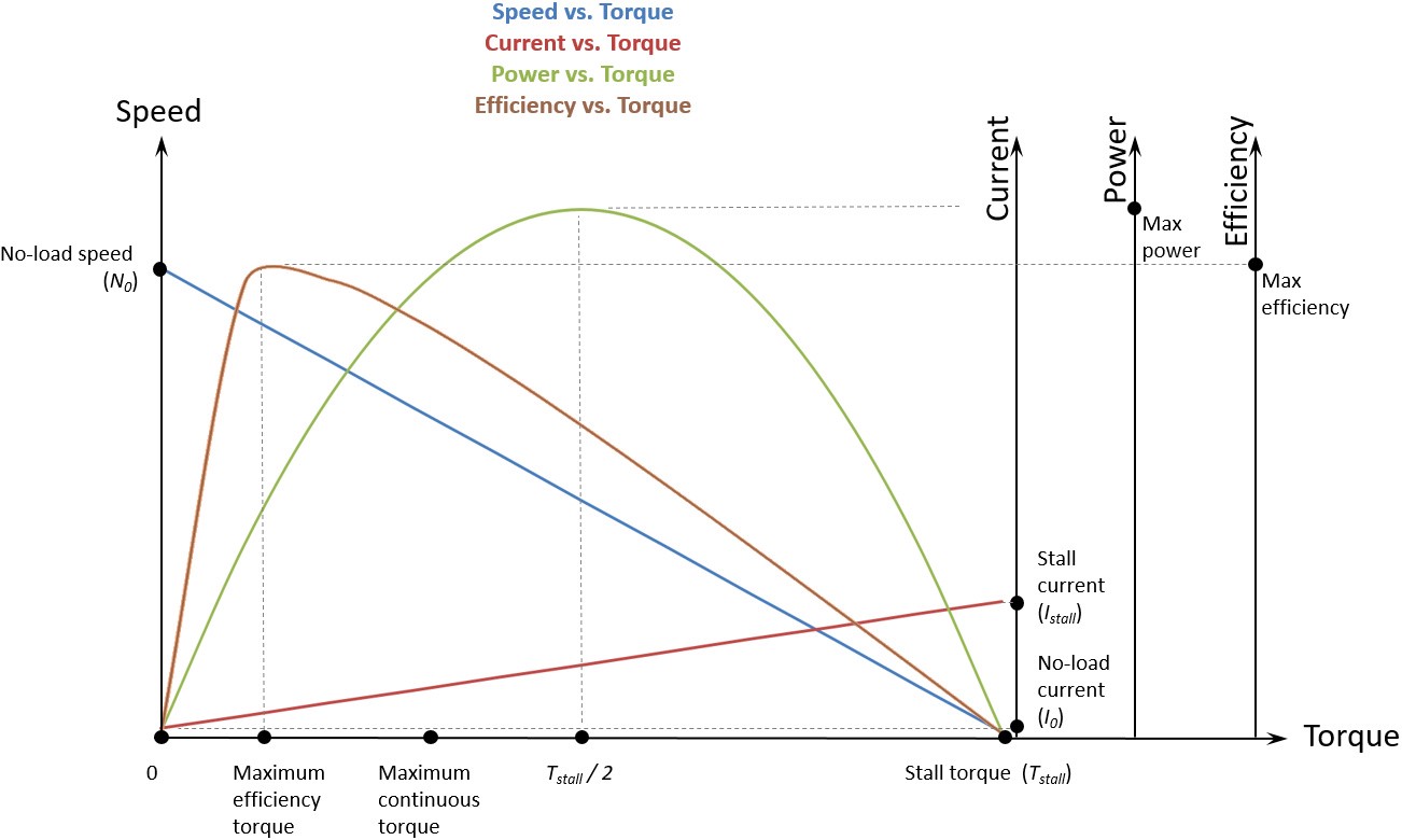
You recognized the blue curve: speed-torque characteristic. Good. Let’s have a look at the others.
- Current curve (dark-red): It’s a line showing the evolution of the current versus the torque. Remember the speed is linked to the torque (the more torque, the less speed)? Here we have a new thing: the more torque, the more current. If you take the problem upside-down, it’s kind of logical: at constant voltage, if you add more and more load to the shaft — like your hand trying to stop it spinning — , the speed will decrease, and the motor will consume more and more current to overcome the mechanical resistance of your hand — which is torque — and keep rotating.
While voltage is an image of speed, we observe now that current is an image of torque.
I take advantage to introduce to you a small yet important formula:

Here KT is the motor constant (N.m/A), I is the current (A) at the time you want to know the torque T (N.m), and I0 is the no-load current (A). Some retailers simplified this equation by erasing I0 from it.
- Power curve (green): This is a curve of the output power, expressed in Watts. It is a mechanical power. It’s calculated according to speed (S in rad/s) and torque (T in N.m):

- Efficiency curve (brown): This is the ratio between output power and input power— current A (A) times voltage U (V ):

Some people observed that the best efficiency is provided at a value of around Stall torque / 7. Like for the maximum continuous torque at Stall torque / 3, this is not a golden rule, but a mere observation that doesn’t apply for every motor. Be careful with these.
This is as far as I will take you today, and yes it is a lot to process. You can stop reading here if your headache is too strong. What I will talk about next are some random but useful comments about the datasheets you can encounter in the wild. Feel free to read it too if you want to know more about it.
Also, some side notes are written at the end of the post.
Thank you for reading. Please clap it up!
Nominal or rated?
In various motors’ datasheet you will be likely to read data like Nominal voltage or Rated voltage — or speed, torque and current.
Most of the time, nominal voltage is rated voltage, regarding motors. It has the same meaning, i.e. the voltage for which the motor is designed to work, at normal conditions. It’s just two ways of saying the same thing.
However, in some cases (e.g. on electronic component’s datasheet) both words won’t mean quite the same:
- The nominal voltage, as put above, is the voltage for which the motor is designed to be used.
- The rated voltage, on the other hand, can sometimes means the maximum voltage for which the motor can work safely without being damaged.
In the case nominal and rated are distincts, rated voltage may be written Rated maximum voltage in order to emphasize the difference with nominal voltage.
The units: hell is real
Let me be straight to it: there are many units. You can literally express a given measure with dozens of different units, and that can be an actual nightmare. It can eventually result, for instance, in the loss of a probe if you make one small mistake. Yes, a Mars probe.
Basically, some people decided a long time ago that life would be much more enjoyable if there were many different ways to express a measure. Therefore there are different systems of measurements: International System of Units — which is the modern form of the Metric System — , Imperial System, US Customary Units, etc. Units are not quite similar from one system to another:
1 meter (Metric System) = 3.28 feet (Imperial System)
Inside the Metric System, almost each unit can be divided or multiplied by 10 (resp. deci- or deca-), 100 (centi- or hecto-), 1,000 (milli- or kilo-), etc., or even 1,000,000 (micro- or mega-), and more. For example, 100 meters is 1 hectometer.
As if it wasn’t enough, you’ll see that for units like torque in Metric system, some datasheets provide a N.mm torque, for example, while others express torque as mN.m. In that particular case it’s exactly the same, because it’s Newton times millimeter (not a division).
EDIT: Oh, and there are some people that would rather say meter-Newton (m.N, don’t you forget that dot, I didn’t say millinewton mN) than Newton-meter (N.m). As it is a multiplication, they… can.
These are far too many reasons to make mistakes, miscalculation, misinterpretation, well, a lot of mis-. Not to mention the actual wars between these different systems’ users.

Therefore, some datasheets will provide (for instance) a torque measurement in kgf.cm (3), others in N.m, and some others in ozf.in (4). So don’t forget to convert your values in the wanted unit before to manipulate them together; always be wary and double-check your work if you really love your satellite.
In order to avoid mistakes, I use a very useful online tool called Translator Cafe, which is trying to save the world everyday.