
This post will introduce the basics of PID control and why it comes in handy for robotic applications. Discover here an introduction to PID control with DC motor. You don't need much background to read this, but knowing the basics of motors is always a good idea: my previous posts on this subject are listed here: Welcome to the jungle.
Now it's time for serious business.
You already theoretically know how to change the spinning speed and direction of a DC brushed motor — if not, you have to read a few posts (see above) to get quickly updated.
Yet, you may find that some improvement is needed if you want to give your motors — your robots — some robotic behaviors.
Robotic behaviors what are they? It can be the fact of being autonomous: no remote control. Also, it's how a robot reacts with its immediate environment.
Let's take an example: you managed to design and produce this nice rover of yours, you casually build a rocket to put it inside, then successfully leave Earth's atmosphere and get your rover safely to the ground of Venus in no time. That's quite a good job. But at this point, your rover is only reasonable to be radio-controlled from your comfy sofa on Earth, so allow me to wish you excellent skills of patience — and a whole set of cutting-edge technology. Yes, now that you think about it, you'd instead have made an autonomous rover.
In this example, being autonomous for the rover is living its own life while exploring the wonders of Venus. What I call environment is, for example, the load at the end of the rover's robotic arm that will apply a force to its joint — hence a torque; it's also the rock under its 7th wheel, or the slope of the steep mountain it's trying to climb to see the view that will reduce its programmed speed, etc.
Your rover must get along with these factors and continue being a rover even though they all kindly but firmly work together to try to prevent it from doing whatever you programmed it to do on its brand-new planet.
Life is hard on Venus.
Train yourself on PID controllers and Luos at the same time!
Different articles follow this one and tell you more about PID control. At the same time we write blog articles, we create an open-source and real-time orchestrator (Luos engine) for distributed architectures; embedded developers can easily design, test and deploy embedded applications.
Don't hesitate to try our technology by following our getting started tutorial. Three steps are needed to become a Luos user!
How to be autonomous and get along with the environment?
Getting autonomous (for a robot, that is) involves you writing a kick-ass programming code that will cover all the single actions you want your robot to do and all the possibilities of a wrong turn of events that could happen in its life.
This code could also include some deep-learning parameters so that your robot has its evolving intelligence. The goal is to act according to what it is supposed to do and its external environment.
If I summarized, you need to give a purpose to your robot and put a brain inside it to manage to fulfill it.But let's not forget I'm discussing the subject of DC brushed motors in robotics, not every part and every aspect of a robot. So I must narrow the topic to this question:
How to get a motor being autonomous?
We can now talk about control loop feedback system.
Note: Here, I use the same word — control — that in the post How to stop being controlled by your DC motor: reverse the roles! (part 1: direction and part 2: speed). Control is a generic word, and the control I'm talking about today is closer than engineering control, which is more complex than giving a simple speed order to a motor.
Let's first define the system as:
- An actuator (for example a motor) and its control board (e.g. this board)
- A sensor (speed, torque, position, etc.)
- A micro-controller board
All of them must be supplied with proper electric energy. As a user, you want the actuator to reach a value, that is called a set-point.
A control loop feedback system is a system that runs in a close loop, with a set-point to reach. The command given to the actuator to reach the set-point depends on the feedback. This feedback consists in the actuator’s value measured by the sensor and compared to the set-point value. The resulting error is computed and re-injected into the initial order as a command that automatically corrects and adjusts the value of the actuator, in order to reach the set-point.
Applied to the motor-sensor-system I defined above, it follows a simple recipe (please note it’s highly simplified for now):
- An initial order is given to the motor (for example: please spin at 10 rad/s).
- The sensor retrieves the status of the motor (the motor is spinning at 8 rad/s).
- The error is calculated (10 minus 8 equals 2).
- The error is re-injected and computed into the initial order (Please go 2 rad/s faster, if it’s not too much to ask you).
- And so on.
This illustration will help you understand:
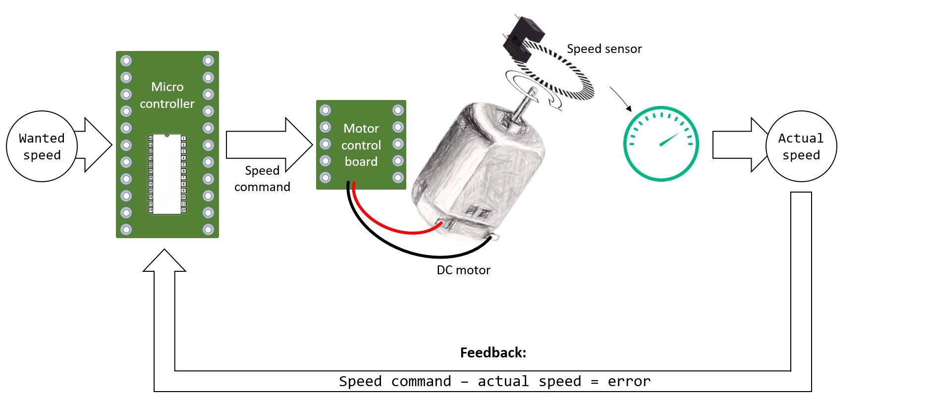
Now you see through this example how the speed is controlled: the system will try to reach Wanted speed (set point) by computing the error and re-injecting it into the initial command. If someone has the brilliant idea to add some load on the motor's output, the system will detect the change of speed due to that load, the error will rise, and the correction will be higher.
This is an adaptation to the environment, called a feedback loop.
There are different ways of controlling a DC motor. Speed-control and position-control are two common examples, but torque-control is also possible. You can even make a temperature- or a noise control if you wish. Logically enough, an appropriate sensor will be needed in each case — i.e., a speed control will work well with a speed sensor.
How can you apply that control loop feedback to your motor? You will use a PID controller.
PID control: What is a PID controller?
A PID controller is an excellent example of motor loop control (though it can be used with various things, like a kitchen oven or a space-exploration rocket) and is widely used in robotic applications.
Why did we use the word controller in PID control?
A controller is a device, program, or set of instructions that alter the output of a system in response to changes in the input. The word controller in PID control indicates that the controllers constantly monitor the error and adjust the input to the system to reduce the error.
First, let's emphasize something: how does it look? If I run into a PID in the street, will I recognize it as one? PID can be hardware (with resistances, doors, wires, etc.) or virtually nothing but a code. The second case is the most common because PID can be implemented in a micro-controller.
Discover what is PID controller, with examples
The proportional-integral-derivative (PID) controller is a control loop feedback mechanism widely used in industrial control systems. A PID controller calculates an error value as the difference between the desired set point and a measured process variable. The controller attempts to reduce the error by adjusting the process input. The three PID controllers—proportional, integral, and derivative gains—are adjusted to achieve the desired result. A PID controller is an example of a feedback controller.
How does PID control work?
Now, that code you're writing with obvious delight is part of the program uploaded in the micro-controller. The micro-controller then orders the motor control board, which is applied as a power signal into the motor. You already knew that, right?
A PID control can quickly and accurately return a response to changes in the set point, making it a popular choice for industrial process control. However, because a PID controller is constantly adjusting the input, it can be susceptible to noise and disturbance in the process.
But what is a PID programming code?The three terms in the PID controllers name stand for the three types of feedback that the controller uses to adjust the input to a process:
The term PID stands for proportional, integral, derivative.
They are the three main components of the code (associated with three respective constants (PID term) that I will talk about later).
These three terms (components) will be calculated in function of the error given by the sensor. Let's call these components functions to simplify things: e.g., F_i(e) is the integral function of the error e. The original target has reached the set point.

Note that this kind of command can sometimes be simplified into a PI, PD, or P command. It depends on the system you're working with, as some of them don't need the full PID command to work correctly:

Note: I choose to say nothing much more right now about these three functions f. We consider them at the black-magic box, for now, discussing them in the following posts. Let's say that if the error is null, the functions are null.
Different tuning methods can improve the closed-loop system's performance. The most common tuning method is the Ziegler–Nichols method. PID control has been used in many industrial control applications, such as temperature, pressure, speed, and position.
For each application, tuning is required to achieve the best closed-loop performance. The PID controller was first proposed by John G. Ziegler and Nathaniel B. Nichols in the paper "Optimum Settings for Automatic Controllers" journal Transactions of the American Society of Mechanical Engineers Conference.
Here is a new example:
You want your motor to stop fooling around, to get its life on track, to spin at a rate of 50. No matter the unit, it can be 50 ETR/μC (Elephant-tail rotations per micro-century). I don't even care—just 50.
Note: the following is simplified pseudo-code, not written in an actual kick-ass programming language.
- Your desired speed: setPoint = 50
- The actual speed of the motor: sensorValue
- The speed command with the PID parameters in function of the error: speed = Fp(error) + Fi(error) + Fd(error)
- In the very first loop, the motor is not running:The first command is speed = Fp(0) + Fi(0) + Fd(0) = 0>> sensorValue = 0>> error = setPoint-sensorValue = 50–0 = 50Error is 50. Big.
- The associated command changes in the second loop, and so the motor has began to spin, it’s rotating at 5, that’s why the error is a bit lower.speed = Fp(50) + Fi(50) + Fd(50)>>sensorValue = 5>>error = setPoint-sensorValue = 50–5 = 45
- On the third loop the motor has accelerated a lot.speed = Fp(45) + Fi(45) + Fd(45)>>sensorValue = 60>>error = setPoint-sensorValue = 50 — 60 = -10The error is negative because the motor is spinning too fast now.
- The command to correct that on the fourth loop:speed = Fp(-10) + Fi(-10) + Fd(-10)>>sensorValue = 50>>error = setPoint-sensorValue = 50–50 = 0
On the fifth loop, the micro-controller is quite happy because the motor is obeying. Good.
So it will provide a null command speed = Fp(0) + Fi(0) + Fd(0) = 0, because the error is null. But too bad: the motor, receiving a null order, is slowing down. This will result in a rising error, a new positive command, and so on. In the end, the motor is getting orders to keep to the set point value whatever happened.
Viewed on a curve, it will look like this:
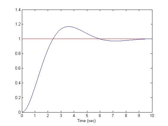
We see that the curve — the motor speed versus the time — is trying to reach the set point value 1. Don't worry; we will discuss more in the next following posts about PID control. To access directly, follow these links:
That's all for now.
To summarize, keep in mind that a PID controller is a widely used control loop feedback system — written as a code most of the time — that allows your motor to reach a set point value (of position, speed, etc.) and to keep it that way as long as you don't change this value. It uses a maximum of three main functions to correct the command — Proportional, Integrate, Derivative — which values change in function of the error between the set point and the actual measure.
We will dig in these proportional, integral, and derivative components on the following posts. We'll look at the maths behind PID control and how to adjust the three constants to get the desired behavior from our motor.
PID control and many other projects are waiting for you on our blog, so don't hesitate to bookmark our content and join our Discord community
Still on the same subject, read now the following article on the PID: the P as in Proportional.
Glossary
PID controller: A PID controller is a control loop feedback mechanism used to adjust the controller output to reduce the error. The PID controller calculates the error, proportional gain, integral gain, and derivative gain to achieve the desired result. It can be used in different terms to control temperature, pressure, speed, position, or other physical variables. A PID controller can be used to regulate the speed of an electric motor, the position of a robot arm, or the temperature of a furnace.
Process variable PV: The process variable (PV) is the measured or sensed value of the controlled process. The process variable is input to the PID controller to calculate the error.
Desired set point (ds): The desired set point (ds) is the expected value of the process variable. The desired set point is set by the operator or controller and is used to calculate the error.
Error (e): The error (e) is the difference between the desired setpoint and the measured process variable. The error is used to calculate the controller output.
Controller output (CO): The controller output (CO) is the adjusted process input. The PID controller calculates the controller output to reduce the error.